
I fitted new core plugs today into all the open core holes. These come in a kit from the MGOctCC so you have no excuse. They are convexed (slightly domed) and to fit them you FIRST ensure the hole’s edge is really clean. Then put a TINY amount of silicon sealer into the corner of the hole all round, so when the core plug is fitted it seats on it.
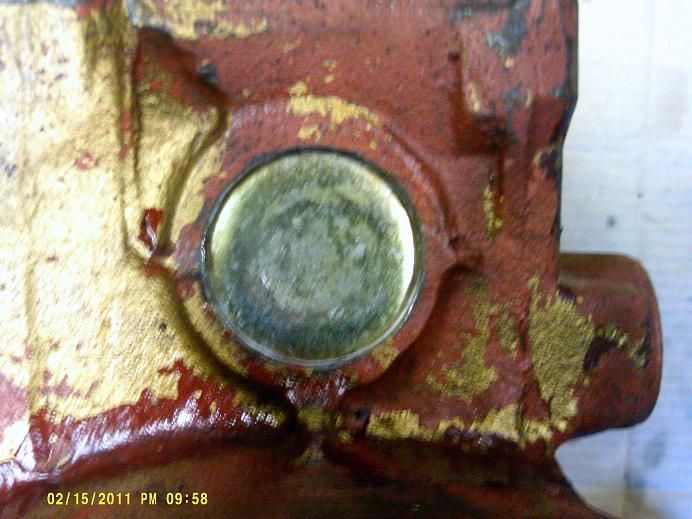
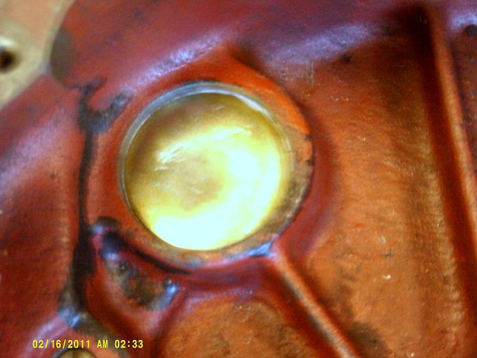
Now take a big hammer and hit the centre of the plug hard a few times to flatten it a little. This, 1) makes a loud bell like noise to annoy your neighbours, 2) wakes up the cat asleep on the dirty oily rag pile and 3) expands the plug outwards to fit tightly into the hole. If you are unlucky enough to have one leak later when you run the engine (though this is a million to one chance if you seal it as suggested) you will need a handy bottle of Holts Radweld ready, found in Halfords. Note also it is bound to be that core plug at the rear of the block where you cannot get to it.

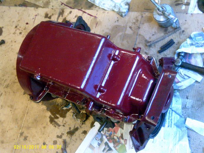 All the following jobs are done with the block upside-down, standing on its cylinder head face on the garage floor. I put old cardboard boxes down as a ‘soft’ surface, carpet would also do. The next job also involves a ‘core plug’, but not one that holds water. This one keeps the oil in and lives behind the flywheel. Time to trial-fit the new camshaft. As the bearings seemed in excellent condition I am going to re-use them; few camshaft bearings wear badly. So I passed the new cam in through the front of the block only to find it would not enter the very rear bearing. Sod it! I then tried the two halves of the centre bearing on the cam’s centre, again they stuck fast. So I micrometer-measured the two camshafts to compare them. The new cam’s bearing journal diameter was just 0.002” bigger, but enough to be too big for my blocks bearings. Two-thou is very little, ( your newspaper pages are three-thou thick) but huge when you come to running clearances.
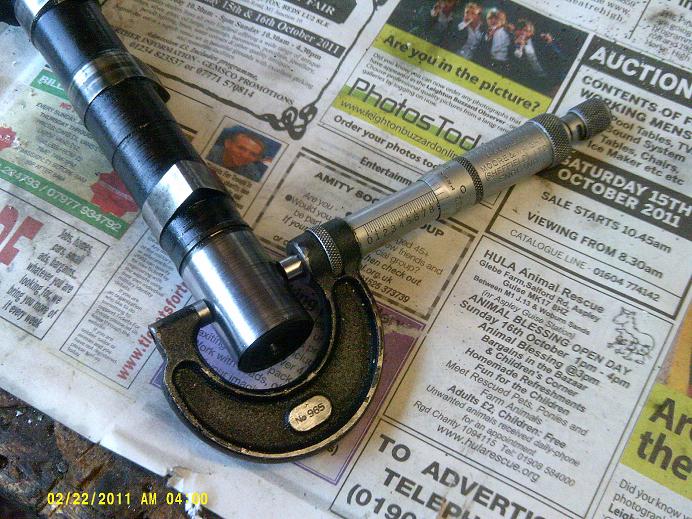
 The cure was to buy an expensive adjustable-reamer. But then I had an idea, as the centre bearing is in two halves, I clamped it to the camshaft with a jubilee clip and rotated it by hand on the bench. This ‘polished’ the bearing’s surface sufficiently to see where metal needed removing. As the cam has the valve-springs pushing downwards in it, via the push-rods, the bearings were worn very slightly on their bottom half; the only ‘touching-areas’ that showed up were on the sides. So I guess the block’s bearings were about two-thou ‘oval’. So I dug out an old half-round, six-inch file and ground it up into a scraper (nice hard carbon steel). Scraping bearings is a very old skill and necessary on older white-metal cast bearings (but not normally on XPAGs!)
 By scraping off about a half-thou at a time from the ‘high-spots’, then refitting them with the jubilee-clip I soon had a nicely fitting bearing. So I then removed the core-plug from inside the bell housing that covers the end camshaft bearing and took out a similar amount of metal from its sides with my scraper until the camshaft slid in smoothly. Real olde-fashioned fitting this. The scraper would remove a sliver of metal about a half-thou thick from the ‘high-spots’. Once I could get the camshaft to enter its rear bearing I found the larger front one already fitted perfectly.
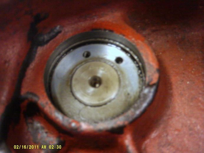
 So I fitted the two centre ‘halves’ to the cam’s shaft and pressed it back into the block using the cam itself with a 1/4” block between it and the cam lobe. As this centre bearing is drilled for an oil feed it is VITAL you fit it the correct way round, AND that you fit it with the locating hole for the bolt facing the bolt’s threaded hole. There are two holes in one side of the bearing to enable you to rotate it a little to line up the bolt’s hole. Note if you fit it wrongly the oil feed hole will face 30 degree away from its feed hole and NO oil will get through. Double check before you go ahead here. Now fit the oval plate that holds the camshaft in with its two bolts, there should be about 0.003” end-float. Do not forget to clean out the little oil drain hole underneath the rear camshaft bearing before you fit the new core plug as per cooling system.(See photo’s at top of page)

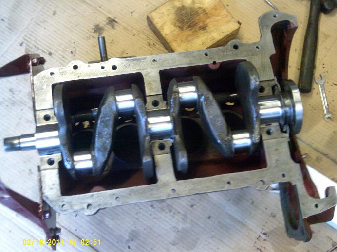 You will all have read, or heard of, the statements in the Haynes series of manuals that, ‘Assembly is just a reversal of stripping’. Yes, I should Co-Co! Because once the camshaft was fitted, the next thing was the crankshaft itself. I sincerely hope that you remembered that the flywheel cannot be fitted with the crank in its bearings; the bell housing will not permit it!
So, loosely fit the flywheel to the crank BUT not yet– ONLY ONCE YOU HAVE ENSURED IT ROTATES in its new bearings. So you are going to have to fit and remove the crank a few times yet as the centre bearing’s thrust faces will require some work to get the correct end-float.

 I refitted the six huge studs into the block using the age-old two-nuts locked together system. Make sure all the main bearing’s fitting surfaces are spotless. As you will have already double-checked you have a set of +0.040” undersize shells for your 40 thou undersize crank, fit the correct shell bearings to the block and their respective caps, this may need a few taps with a wooden block to get them to seat.
MAKE SURE you have the right shell in the right half, though most have holes duplicated, some sets only have one side with oil feed holes in. If you fit a blank shell to the block half no oil can get to the bearing! Note these XPAG main bearing shells are located by a ‘dowel’ in the cap.
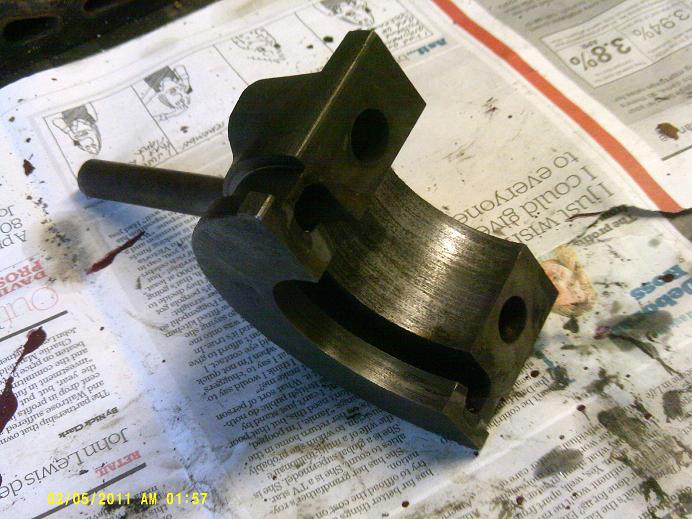
 I did No1 and No3 first because I knew about the centre bearing’s need for adjustment. Always add a bit of oil to any new bearing surface. I tightened down each cap individually to ensure the crank would spin easily. It did. But when I tried the centre bearing fit, the crankshaft would not even drop into the bearing. This is because for re-ground cranks, the centre bearing’s shells are supplied too wide. You need to ‘fit’ them by again filing off metal from the thrust faces, a few thou at a time using the old shells as a guide.
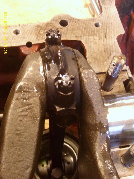 I took the excess metal from the forward face so as to leave the nicely machined one on its rear face; this is the one that takes the thrust of the clutch working. DO NOT file them to the old size, (the width of the thrust faces,) because your crank has been re-ground so the width is probably a few ‘thou wider now. You will need to remove and fit the crank and shells a few times until you have the required end-float of between 0.003” to 0.005”. The idea of ‘end-float’ or a ‘working clearance’ is to permit oil to get in and allow for any expansion. Take care to remove all swarf (this is why I do all the filing on the bench, not inside the engine!) With the crankshaft free in its bearings but removed, I then I fitted all four pistons the correct way round, with their piston rings, into each bore.

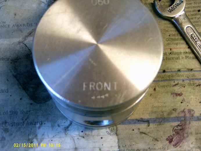 Why fit them now? Try doing it with the crankshaft in! (It can be done but my way is much easier and you do not break any rings.) Fitting the pistons now means you can use the tapered bottom end of the bore to guide the rings into it easily. Use lots of oil in the bore and on the piston, especially in between the rings. Each piston will be a very tight fit. With my oil can I pumped oil into the dry oilways of the crankshaft and block, priming them.

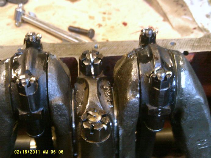
 Now with the crank lowered into its three bearings I could clamp down those huge nuts on the main bearing caps HAVING FITTED THE FLYWHEEL first, loosely. We will tighten them in the next paragraph but one. Tighten up the main bearing cap nuts to about 750 lb/in ( 8.6 m/kg) then on to the split-pin hole if it is not lined up. Fit the split-pins to lock the nuts.(Right, it is now you find out you have fitted the studs upside-down…so remember the threaded end with the hole in does NOT go into the block.)
The con-rod big ends will now be sitting underneath the crank’s webs. Starting with No.1 big end, fit the new shell, making sure it is the one with a hole in so the oil will spray up the cylinder’s bore. Again most bearing sets have a hole in all the new shells (fail-safe), but double check. The shells are located to one side of the con-rod big end, and the caps location lug is fitted so they are on the same side (remember these con-rods are machined with their individual caps fitted, under no circumstances mix up the caps, or fit them the wrong way round.) Using new nuts and bolts, bolt up No.1 to its journal.
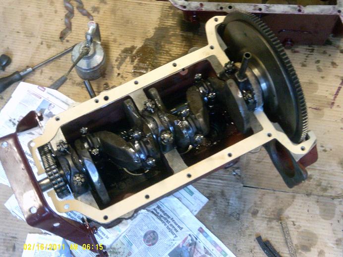 Test the crank will move. It will now be considerably stiffer that when you just had the main bearings, with that piston in its bore there is much more resistance. Now do No.4 (as it is on the same plane) and then 2 & 3, testing each one for free movement. If the crank locks up, double check you have the big end cap on the correct way round. If all machining and clearances are correct, everything should be OK, BUT by the time you fit No4 and try to moved the crank, it will take an apprecable effort. I had to use a crow-bar through the clutch cover bolts on the flywheel, but you can ‘feel’ it is the pistons as the crank moves easily at TDC and BDC, but very stiffly at 90 degrees to either, pistons half way up each bore. You can also hear those piston rings on the honed surface. Remember to oil all the big ends, again filling any oil feed hole in the crank to prime it before you fit the big end caps. Tighten up the big end nuts to 320 lb/in (3.7m/kg) and split pin them as the main bearings. Always tighten to the split pin hole, NOT LOOSEN.
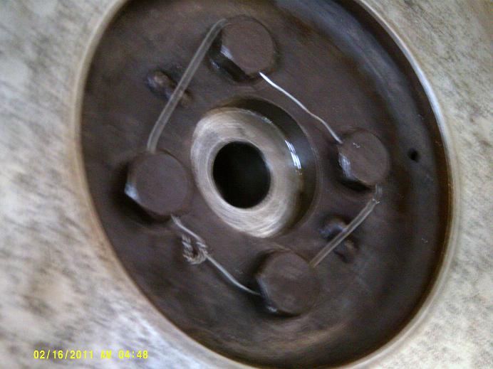 Now put a block of wood by a crank web in the block to lock it, then tighten up the flywheel bolts tight and wire-lock them so the wire ‘tightens’ them. Two dowels locate the flywheel. If the rear crankshaft bush fell out as mine did, refit it now with some Studlock or tin it with solder on its outside and press it back in. Or if it is worn, fit a new one. Fit the clutch cover with your new or relined clutch plate using an old first-motion shaft to ‘centre’ it up, or a bit of wooden broom handle turned down to fit the clutch centre and the bearing inside the crankshaft. ‘Centering’ the clutch plate now saves lots of temper and swearing later on. It was as I was fitting the clutch I noticed two of the bell-housing threaded holes were in a poor condition. The threads in the alloy sump were all but stripped.
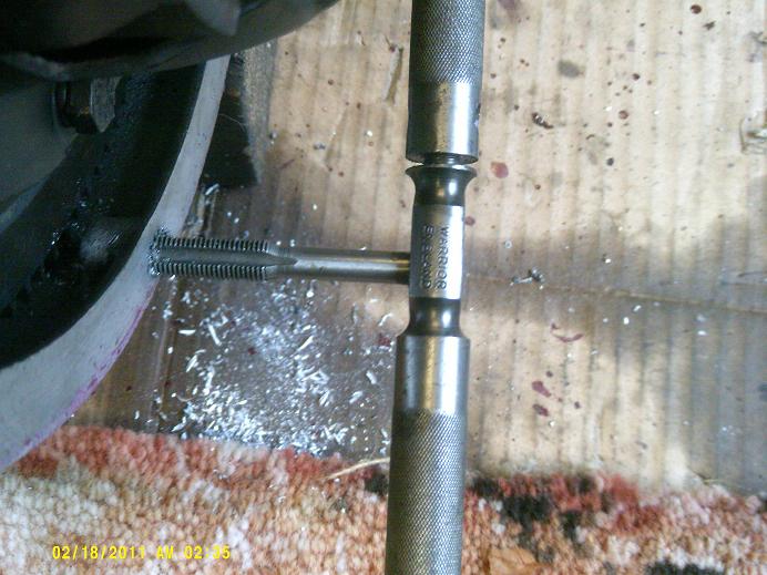 So I tapped the holes out to the next size up, and had to drill out the corresponding holes at 4 and 5 o’clock on the gearbox half so the bigger bolts would fit. This means my bell housing now has two UNF threaded bolts! For the technophobes my engine is an early one with a 7.25” clutch, but my gearbox is a YB one with a 1” first motion shaft (the earlier 7.25” clutch one is 7/8”). A YB has an 8” clutch with a 1” centre, so I have a ‘bastard’ fitting. I have a 7.25” clutch plate with a 1” centre, luckily early Hillman Minx used them.

 Now you can fit the timing chain and its sprockets as long as you have already fitted the keys to their keyways. But first, using a new gasket, fit the front engine plate that the front engine bearer is on. My new camshaft chain did not have two bright links! So I had to use the workshop manual to paint a bit of silver onto the links 1 and 15 (see page A20 and section A28 in the manual for more info.) so I could line up the two ‘T’ stamped on the sprockets correctly. This means the valve timing is correct. Remember to fit the crankshaft woodruff keys to the cam sprocket shaft and the fan pulley first. If you miss out the fan’ key you cannot time the engine! The camshaft sprocket’s nut is locked with a locking ‘tab’ washer that locates in the key-way hidden under the big washer. Now fit the timing chain tensioner remembering to wire-lock its two bolts. Oil the chain liberally.
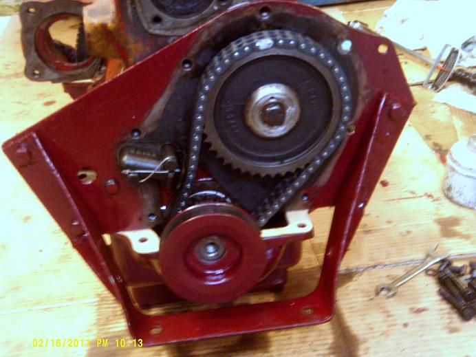
 Hopefully you have not misplaced the little oil-thrower that sits in front of the crankshaft’s timing sprocket. Its dished surface faces forwards and its job is to throw oil away as it spins from the front seal area.
With the crankshaft, pistons, camshaft and chain fitted, we can now fit the sump. You will have cleaned it all up, painted it and obtained a good gasket set. Remove the old front bearing packing from its grove and press in the new ‘short’ bit from the gasket set. The longer bit goes into the timing chain cover. Note one side of the gasket set has a hole in it for the oil feed to the pump. If you are not paying attention it is easy to fit the gasket sides to the wrong side, thus cutting off any vital oil feed! Yes, it has been done. Following the very good picture on A17, and section A42 on page A29, fit the gasket, cork and packing.(The same pictures are in the YA manual but with different numbers!) In every ‘corner’ I use a bit of silicon sealant to ensure a decent seal. Many rear end oil leaks are not from the rear scroll seal at all, they emanate from the corners where the sump gaskets meet the rear bearing cork, or fail to meet.
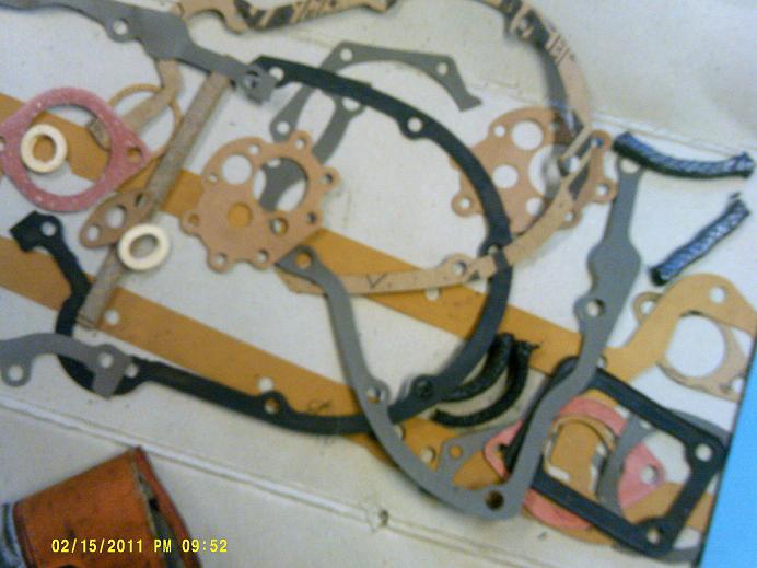

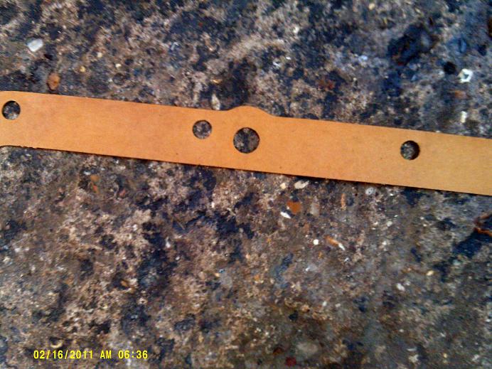
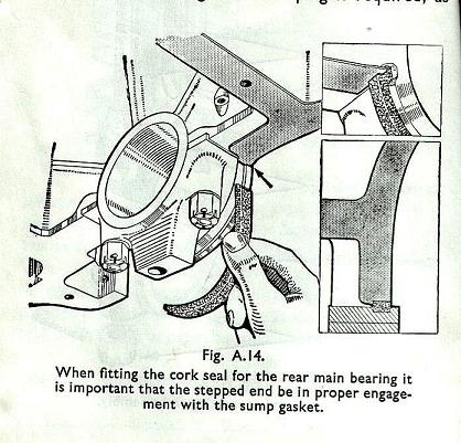
Double check you have the right gasket on the right side, so that the bit with the hole in is over the oil pick up. ( A member did fit the sump gaskets without checking the oil feed up into the pump was clear. He ‘blanked off’ the hole with the sump gasket by fitting the wrong side. He ran the engine without priming it, and ran the bearings….priming again checks you have not blocked that vital feed.)
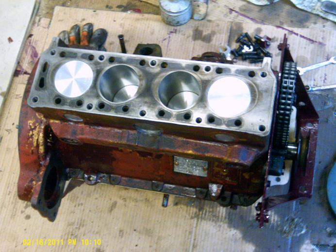

With the sump fitted the block can now be stood back right-way-up on it so you can see the nice, new, shiny pistons. Again with a new gasket and new packing in the crank-nose seal, fit the timing chain cover after first giving the chain a good oiling. Again put some silicon sealer into the corners. As you will need to pull ‘down’ and as well as ‘in’ with the bolts on this cover, do not fully tighten them yet. Fit the two sump bolts last and almost fully tighten them, then the block ones. To do this you will have to fit the fan belt pulley with the bolts all loose which means you CANNOT fit the bolts either side of this pulley until last (you cannot get to them). Oil the pulley’s sealing face. To finally fit those last two bolts you will need to remove the pulley then refit it! (I would love to meet the chap who designed this bit.) If you do not fit the cover with the fan pulley fitted, the packing in each half of the ‘hole’ will not get crushed correctly, and trying to fit the fan pulley later will be fraught with difficulty, ie, it will not go in the hole! Finally, fit the big washer under the starting handle nut, then the nut itself. This will give you the ability to turn the engine over to ‘prime’ the oil system. More of this VITAL bit later.

 The engine is now beginning to look more complete. The oil pump is next. This requires a gasket between it and the block face, but metal-to-metal on its end-cap. Oil the gear drive. Again ensure all is clean and enter the pump’s body into the block so its gear meshes with that on the cam. Fit the gears then the cap, with those long bolts. But BEFORE you fit the cap, load up the gears in the pump body with grease to fill the voids. Once you have bolted on the cap, put about 4 pints of clean new oil in the sump (I put it down the distributor’s hole) and then, with the starting handle, wind the stiff engine over until you get oil gushing out of the pumps feed to its filter (with a later pump with the filter as part of it, leave the bowl off so you can see oil coming out. I cannot stress just how VITAL this priming of the oil pump is. First, it proves you did fit the sump gasket correctly, secondly it lifts the oil from the sump up into the pump, that is why you plugged the gears with all that grease to ‘seal’ the gear teeth. The XPAG has a bad name for being a pig to prime once fitted in the car.
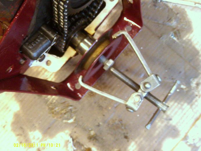

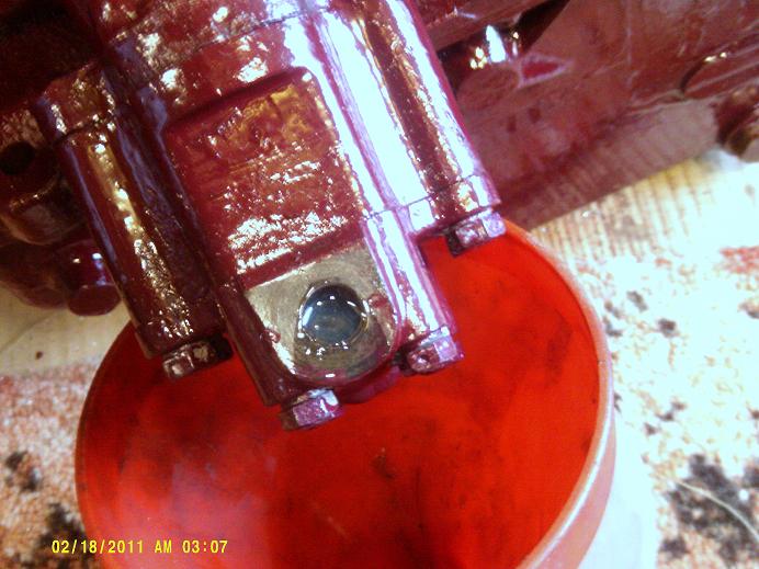
Early engines like mine have no priming plug on the oil pump either. We will be doing this winding-priming bit with the engine installed later to get oil up into the main oil gallery, but as I’m not fitting my filter until the engine is in situ (to give me more maneuvering room with the block) it will have to wait. If you have a later SC/2 engine with the filter as part of the pump, you can do it now. Fit a new filter element then the bowl. Wind the engine over until oil comes out of the oil-pressure gauge connection. Oil is now in the main gallery and the engine is OK and safe to start as oil will feed the bearings.} If you have an early engine like mine, we have a bit more priming to do later. The reason for all this fuss is, if you run that engine without priming it, the bearings will soon run dry, and you will ruin a new crankshaft in seconds.
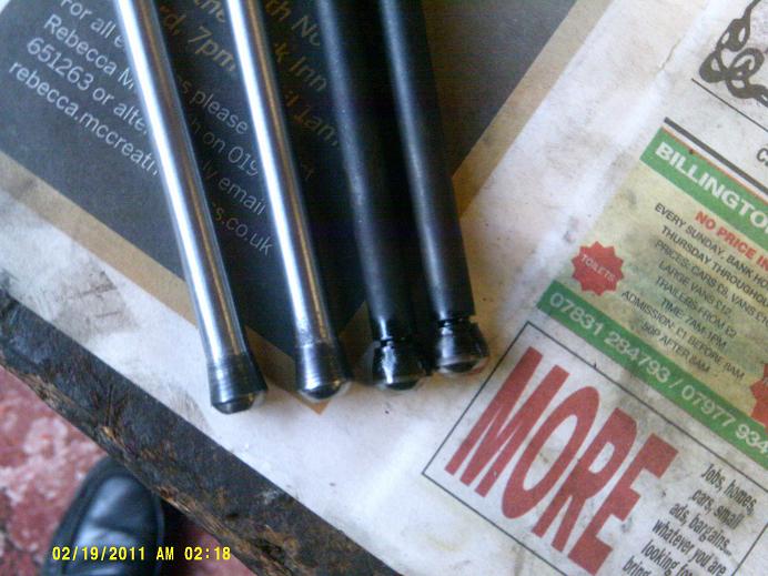
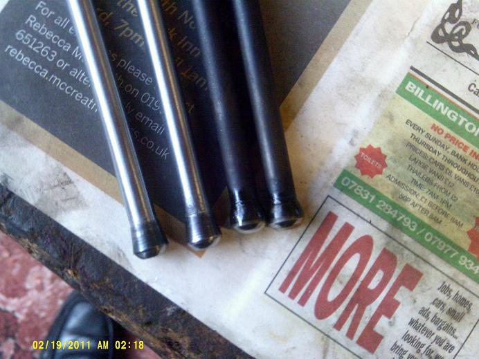
I now fitted the eight cam followers into their holes, oiling each one. The MG OctCC had stuck on a label to each, very sticky labels, it took some time to peel them off. So now with the block assembled, it was time to fit it back into the car. Upon checking the push rods I found two had loose ends, so ordered two new ones. It is common for the ends of these rods to eventually wear loose and the photos should show what happens when you ‘pull’ the ends.
Neil Cairns.