
Please remember that the numbers quoted refer to the Manual mentioned in the Part Two introduction paragraph of this Gearbox article.
To view the captions please hover your mouse over the photographs.
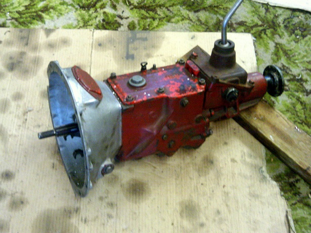

Pulling a gearbox to bits is fairly easy if you follow a logical route. First clean the thing if you have not already done so. I use big sheets of opened out cardboard boxes on the garage floor as a ‘bench’ and old ice cream cartons for all the bits one removes. Have a digital camera handy to photo bits BEFORE you remove them so you will have some sort of reference of how it should look. The first and obvious bit to photo is the selector linkage assembly. You should have worked out what bit does what by playing with the temporarily fitted gear lever; note how reverse is selected. Have a photo copy of page E4 handy on the bench, saves making the manual filthy.
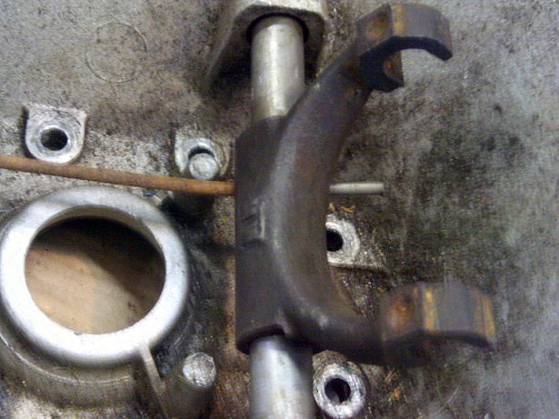

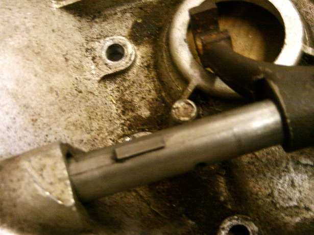
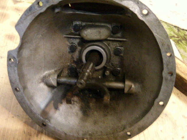
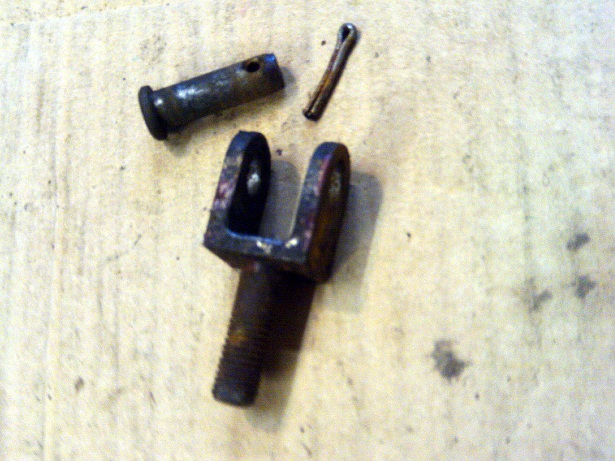
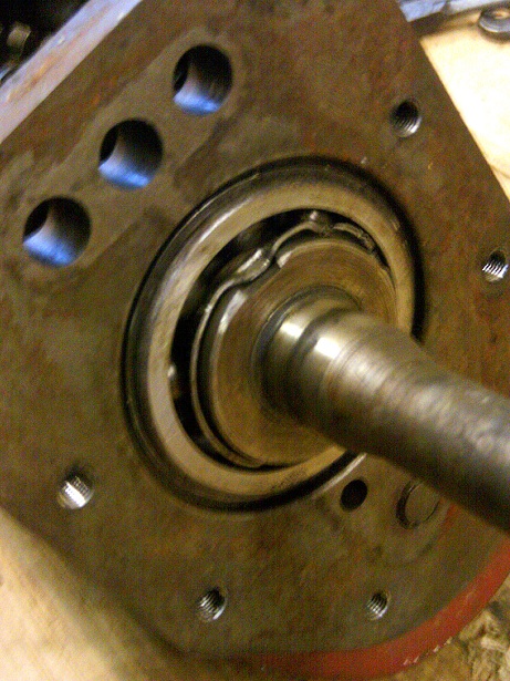
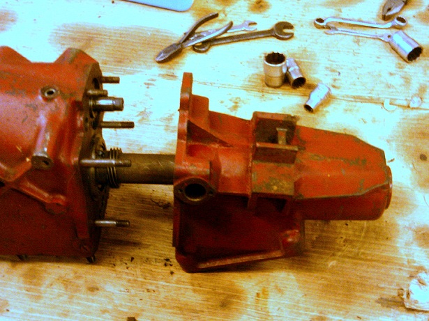
Remove the gear lever and double check the spring inside its cover is not broken. Going to the bell housing, operated the clutch lever outside it and check for slop in the bushes. My gearbox is well worn on the one side here so will need a new or good s/h one. Remove the carbon-faced release bearing, it has a spring clip each side. To remove the clutch release bearing shaft, drift out the pin that holds the bearing fork to the shaft, then tap the fork to one side to reveal a key, remove the circlip from the other outer end then pull the shaft out. There is no need to remove the lever left on the shaft. Undo the eight bolts that hold the alloy bell housing to the cast-iron gearbox. Watch out for any big shims that locate the big first-motion shaft bearing, (item 13), Label the shims for that bearing.


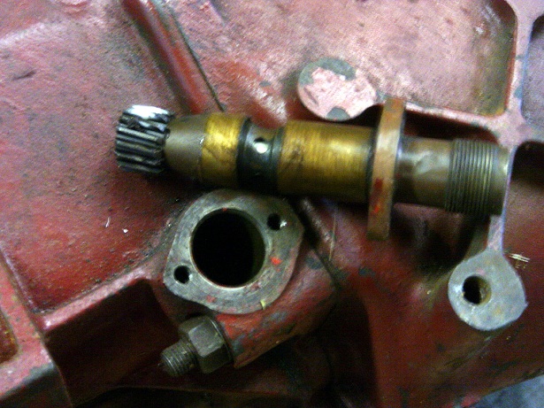
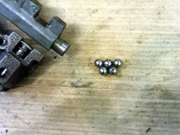
With a socket tap out the old oil seal, it is probably a leather one, add the need for a new one to your wanted list. You will have already removed the top lid (item 7) and will have carefully put the three springs (99) from the detent balls safely in a box labeled up. If you turn the box on its side the three ball-bearings (98, there are five in all) you can see in the three holes might come out, or they might be stuck fast with muck. Remove the dip-stick and put it in a box. Remove the speedometer drive (items 113-114) and the two screws (that should be wired locked).

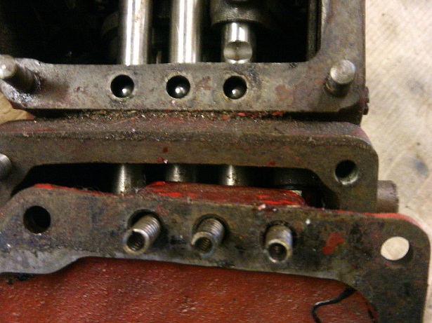
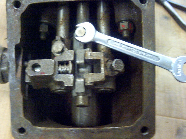
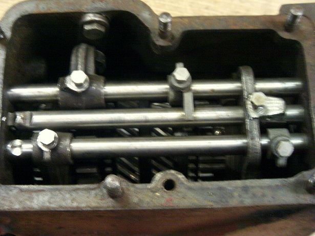
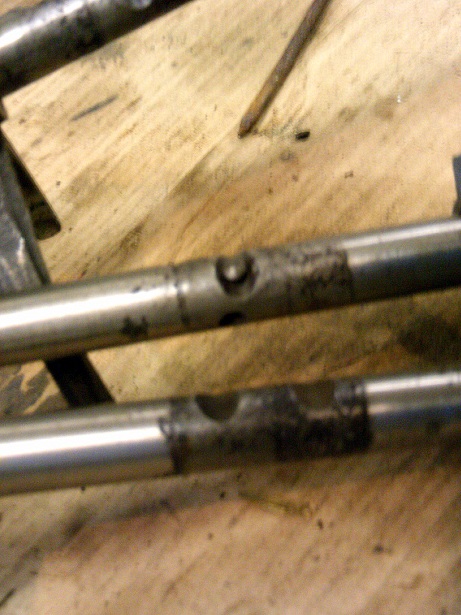
Now undo all the little hexagonal bolts that lock the selectors to the three shafts (square bolts on later YBs) and slide off the ones at the gear lever end. They need wiggling a bit but will all come off. Place them in order on a clean bit of cardboard. Now, work your way with each rod, sliding the rods out to the rear but catching the selectors as they come free. Do one at a time and then re-assemble it loosely before removing the next. You did take a photo before didn’t you? Once they are all out put them safe loosely assembled. Note that the centre rod has a little moveable peg between the detent grooves (see diagram).
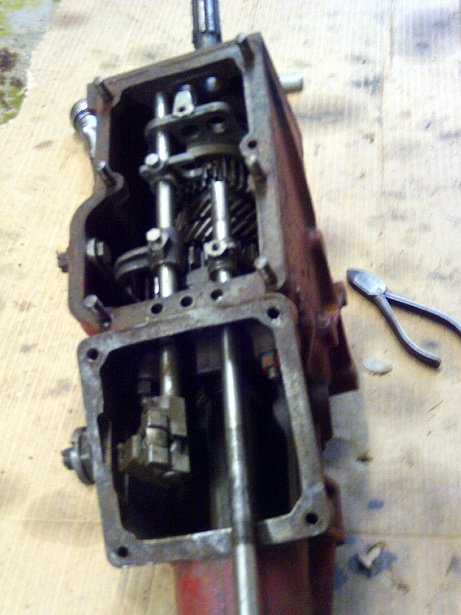
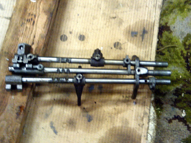
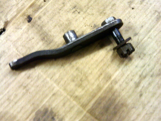
Also note that there is a ball bearing on either side of the outer rods (the other two to the total of five). They are probably in the gearbox now, or on the floor. Find them before you go any further. You did study the reverse selection, so now remove the split-pin from the castellated nut (93), then the bolt (94) and the arm (91). Put them safe.
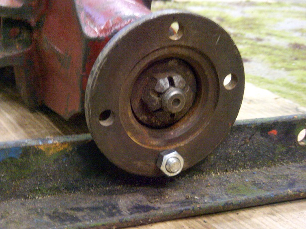

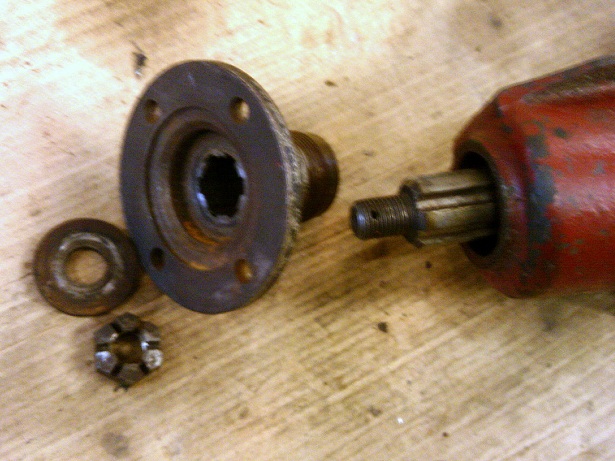
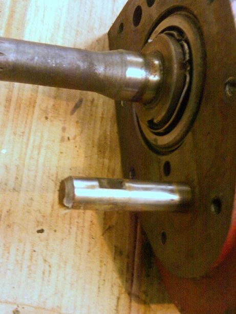
Now get a bit of angle-iron, bolt it to the rear prop-shaft flange (122) as in the photo, remove the split-pin from the big nut (124) and undo it. Catch the washer (123), pull off the flange and put into a box. Now undo the bolt on the very bottom of the gearbox (56) and remove it. It locks in the lay-shaft shaft. Undo the six bolts and nuts that hold on the rear casing (106) and pull it away. Remove the eye-bolt (125) from under it and check the hole in the casting is not cracked (very common).
Taking note of where each washer goes, pull off the rear most bearing (108, it slides off easily). The felt ‘oil retaining washer (110) will remain inside. Pull of the long spacer (46) noting that there will be shims (24-25) at the centre bearing, label them. The speedometer drive gear (112) is only gripped between the spacer and bearing, there is no key slot. 112 will slide off as well. You will now be able to see both ends of the shaft (47) for the lay-shaft (48). Using a long rod tap it out from the rear. You will have to do this to let the lay-shaft drop into the bottom of the gearbox to be able to remove the first-motion shaft. Inspect this shaft carefully, it gets a rough time in the low gears and can ‘spall’, that is break up on its hard surface. Add one to your wanted list if necessary.

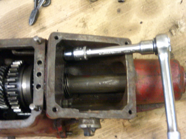
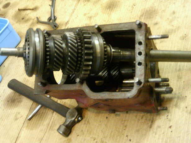
Now put a lever between the first and third motion shafts and part them. Both will move but the front one will come out fairly easily, you may need to use a copper drift on the bearing to get it right out. Watch out for all the needle rollers (18). Collect them all (there are 18) and micrometer them all, if some are worn by a new set. Good ones are 0.1175” to 0.118”. Now go to the rear of the ‘box and carefully lever out the centre bearing (21). You CANNOT get the third-motion shaft out of the rear end of the box, the gears are too big, so you remove its bearing to the rear, and once off you then lift the whole assembly out forward and through the top.
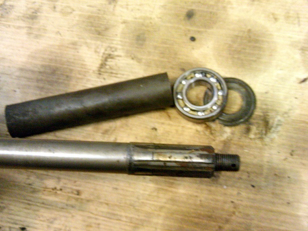
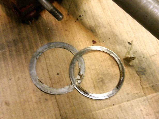
Place the two shafts somewhere clean and safe. DO NOT MOVE THE SELECTOR item 26, leave it on the third-motion shaft. If you move it, the locking ball bearings (28-29) will fly out and (a) they will be impossible to find and (b) a real sod to refit. On my gearbox one of the little springs (29) was cut in two and in the bottom of the gearbox, I never found the ball so it had obviously been assembled without it. (More on this later).

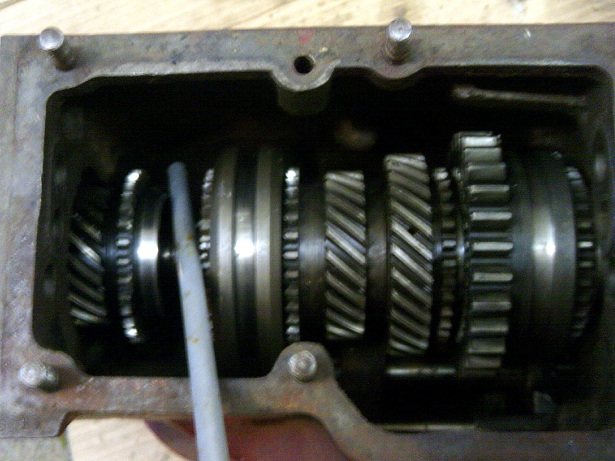
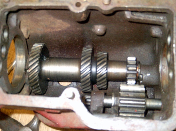
In the bottom of the now nearly empty ‘box is the lay-shaft (48). Lift it out carefully keeping the thrust washers (52,53,54,55) together. Place it by the other gears. Now undo the bolt on the side of the ‘box that locks item (60), the reverse gear shaft. Tap out the shaft and lift out the reverse gear (58). Item 88 and 89, the selector, need not be removed, (mine refused to come out anyway). You should now have an empty gearbox casing.

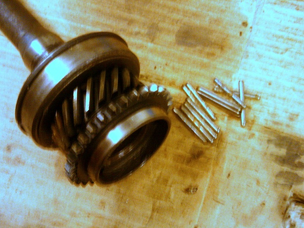

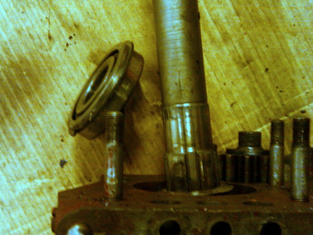
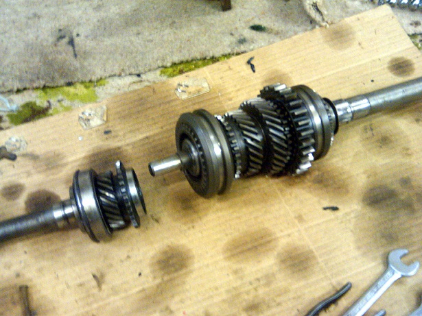
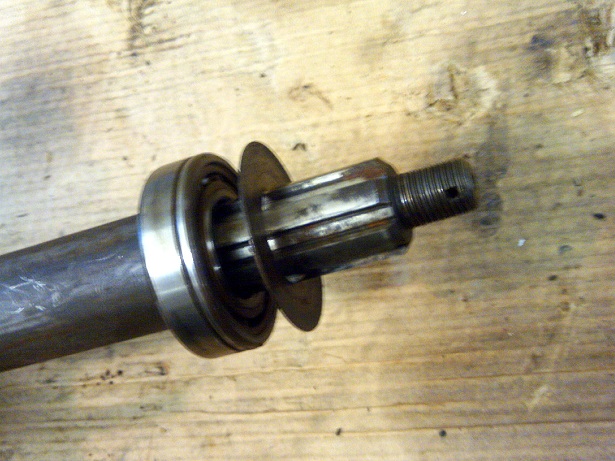
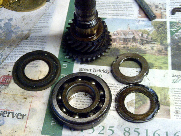
The first motion shaft needs further stripping, but the gear-crowed third motion shaft, if it all worked OK, need not be pulled apart. The ‘first shaft needs putting into a vice fitted with soft jaw protectors (aluminium) and gripped on the splines. The locking washer (17) needs tapping back out of the slot (if it is a bit rough you will need a new one, add it to the list).. Then a ‘C’ spanner is needed to undo the big nut, IT IS A LEFT-HAND-THREAD note. Take note of the assembly order of all the washers again. Now wash all three of the ball bearings (13, 21 and 108) in paraffin, dry them out then check them for wear. If they sound gritty when you spin them and are a little sloppy side to side, they are worn out, buy a new set. If the sound they make when you spin them sounds familiar, it is the ‘zizzz’ you get from the gearbox lever when it is hot indicating worn bearings.


Neil Cairns.
