
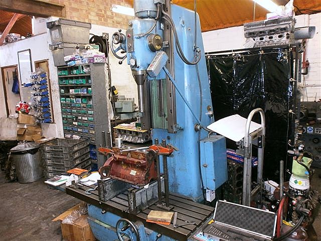
 This is really the time of the engine reconditioners, ‘Headline MK’ of Cranfield Road, Wavendon, MK17 8AS, 01908 582482. Their website address is www.headlinemk.co.uk. You have to supply the parts to be worked on clean of any extra bits, so everything needs unbolting and removing, including the core-plugs. This is so they can measure the thickness of the metal of the bore to ensure it is thick enough to take, in my case, a 60 thou ( 0.060”) over-size rebore.
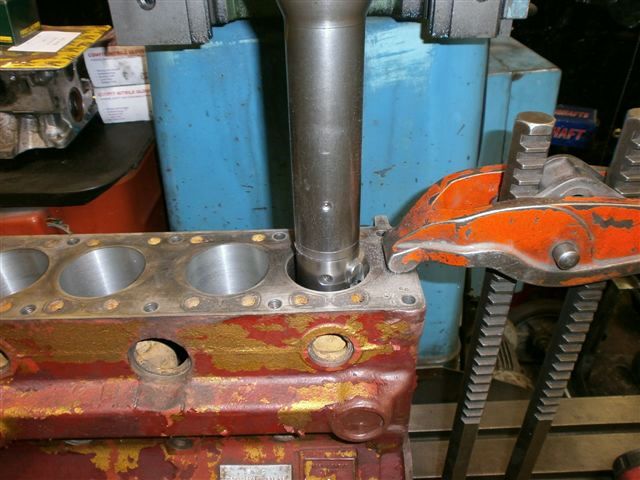
The block is washed clean by them, then bolted to a boring machine that cuts out the metal with a tool-bit. It is a bit like a cross between a lathe up on end, and a milling machine. Each bore has to be centered under the boring head accurately so as to keep the centre-line of the piston correctly over its big end journal on the crankshaft. When the machine is boring out the metal, the tool-bit is cooled with a mixture of water and soluble oil.

 This machining leaves a very fine set of grooves where the tool-bit cut the bore. To remove this rough surface the bores are then ‘honed’ with stones lubricated by oil. The photo’s show the block on the re-boring machine and then on the floor being honed. This ‘polishing’ of the bores produces a very fine finish and means that today we need not go through the laborious actions of a 1000 mile running-in period. 500 miles is sufficient with an oil change.
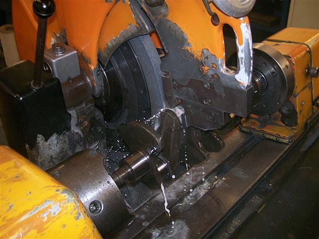
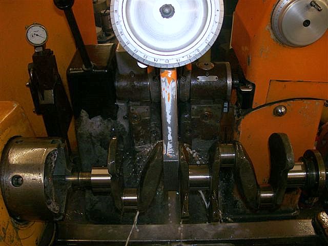
The crankshaft photo’s below show it on a regrinding machine where again a very fine finish is obtained and with today’s machinery, a very accurate finish. It is VITAL that any re-ground crankshaft has the correct radii in the corners. Where the journal’s bearing surface blends into the drop-forging of the crank’s webs, there must be no sharp corners or edges. Any faults like that will produce an area where a crack will start, (as anyone who knows why the Comet airliner’s crashed will tell you; they put square windows in a pressurised hull, eventually the corners cracked and the Comets fell to bits in the sky.)

Also on the machinist’s agenda was to blow out all the oilways in the block and crank. You can help yourself here as the six little hexagonal headed screws along the main oil gallery can be removed and the holes washed out with paraffin. These screws are the ‘plugs’ for the oil-way drillings to the main bearings and the camshaft bearings; note a lot of black sludge will ooze out.
Whilst the block and crank are away being machined, read all the ‘engine’ section of your workshop manual so that you will be familiar as to where data is and what information is given. For instance there is NOTHING in any manual to tell you about trimming the centre main bearing thrust faces simply because no one ever thought these cars would be around in 60-65 years time and regrinding removes metal from thrust faces!
I collected the block and crank five days after delivering them. As mentioned I had to supply a +0.060” oversize piston so they could rebore the block to the correct size, which is 0.0025” ( two and a half thou’) bigger than the piston’s diameter at right-angles to the gudgeon pin just under the oil ring groove. Note for later that each piston has ‘FRONT’ stamped on its crown. This is the side that will go towards the radiator end of the block. The cost of the rebore to +0.060” was £100; the re-grind to -0.040” was £140; add VAT and that comes to just £288. Damned good value I say.
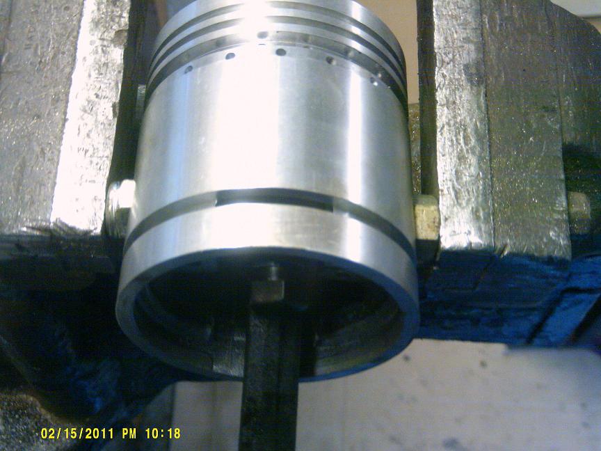
 To remove the old pistons from their connecting rod, you will need a vice to hold it in. With the old pistons it does not matter if you grip them directly in the vice jaws, but with the NEW pistons, only hold them by the gudgeon pin. I use two big nuts each side as in the photo. You need to undo the pinch-bolt that grips the gudgeon

 pin but a socket will not fit as the little end is in the way. So you will need an open-ended spanner as in the photo.
Do one piston at a time, pressing out the old pin (it is not a tight fit, though if you are in a cold garage a bucket of hot water will warm the piston so the pin slips out,) and then fitting the connecting rod to its new piston the correct way round ( FRONT to the front; pinch-bolt away from the cam). Take care to keep each big-end cap with its correct connecting rod. If you fail to do this you will have a terrible time when you try to fit the rods to the crank. Each connecting rod and its cap are machined as one item so become a ‘PAIR’ for life, then stamped with the cylinder number on the side of the big end. Also ensure that the caps have their little shell bearing’s locating lug on the same side as the rods, again if you forget this you will soon have a locked up crank as you assemble it all.
Fit the new piston with its NEW pinch-bolt to the correct con-rod, with the pinch bolt on the same side as the shell locating lug; that is, away from the camshaft when in the engine. The new ‘pins should slip in easily and you only have to line up the groove in the centre of the pin with the bolt. Tighten it up in the vice, holding the piston as mentioned, by the gudgeon pin (for our USA cousins, the wrist-pin). Do all four and as you complete each one just put a tiny centre-punch dot on the piston crown by the ‘FRONT’ letters, one for No1 cylinder, 2 for No2, and so on. It aids correct assembly a great deal later. Do not fit the piston rings yet, they are very fragile and should only be fitted at the last moment.
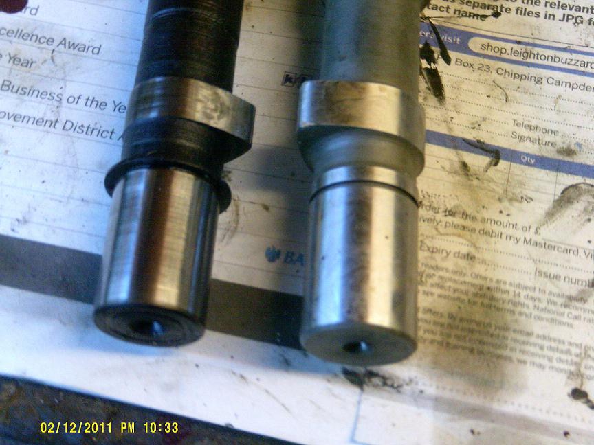
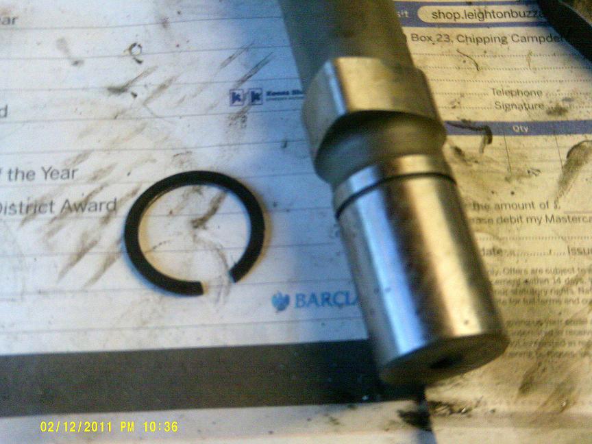
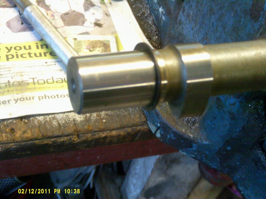
Now remove the circlip from your old, worn camshaft and fit it to the new one. It is there to stop the cam going too far to the rear. Also remove the ‘key’ from where the cam sprocket fits, and fit the ‘key’ into its ‘key-way’ in the new cam.
If you have not cleaned up the main bearing caps, do so now and make sure you know which way round the centre one came off!! If you fit it the wrong way round you will, once again, lock up the shaft. All three main bearing caps are fitted and in-line-bored as one with the block. You cannot fit the front or rear one any other way than they fit, but the middle one can be. If you are stumped here, look at the old carbon marks of the cap, it will have a ‘ghost’ of its fitting on its face and one side will differ from the other a little. Mark it so you know the front! If you fit it the wrong way round, and if it is machined only a couple of ‘thou out, that is a huge miss-alignment; sufficient to lock the crankshaft. The newly ground journal only has a clearance of just 0.0015” to 0.002”.
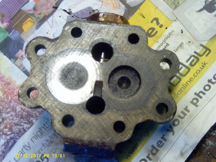

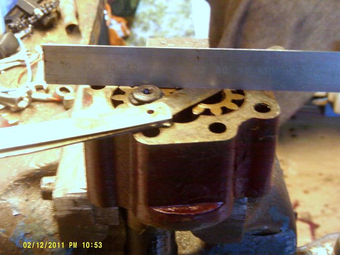
My oil pump is in excellent condition, unworn. But to check if yours is worn, clean it up then test the end-float of the gears using a feeler-gauge, see photo’s above. Anything over 0.003” is too much. You can cure too much ‘end-float’ by either lapping in the pump’s body on a bit of plate-glass, or by buying new gears and fitting them. They may need a bit of machining to get the correct end-float. The pump’s end cap also suffers if dirty oil is not changed. The gears wear into it. Again this can be lapped out on a bit of plate glass. ( Lapped;- rubbing the item on a thin layer of grinding paste on a flat, hard surface, then onto the face it is to eventually be fitted to. You can see where the faces are meeting by the dull grey areas. It all needs to be dull grey. REMOVE all traces of the paste. If you are rich you can save time by getting a machinist to surface-grind them for you.) Note that whilst the pump body has a gasket between it and the block, the pump’s end plate has no gasket; so its surface finish must be excellent AND flat. Make sure you remove all traces of grinding paste.
 Mine is an early type oil pump of the YA/YT (SC engine); the YB had a later one that has the oil filter as part of the casting, (SC2 engine) so I have external oil pipes to a separate ‘full-flow’ oil filter. Remove the oil-pressure-relief valve, it is under the big brass nut on the end-cap. Inside you will find the bits shewn on page C2 of the YB workshop manual. (If you have no manual, look at the oil pressure articles amongst the tech-pages of this website.) If the ball bearing has any marks on it, renew it. If you were suspicious about your oil pressure, renew the spring.
Note also that early oil pumps do not have a ‘priming’ plug’, but we will get to that vital task later.
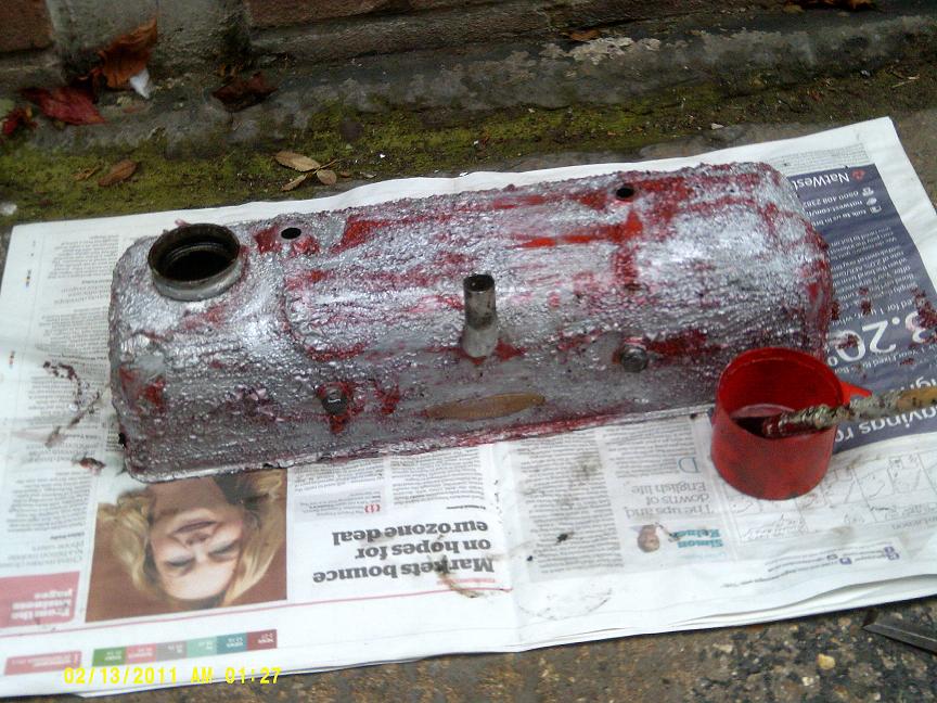
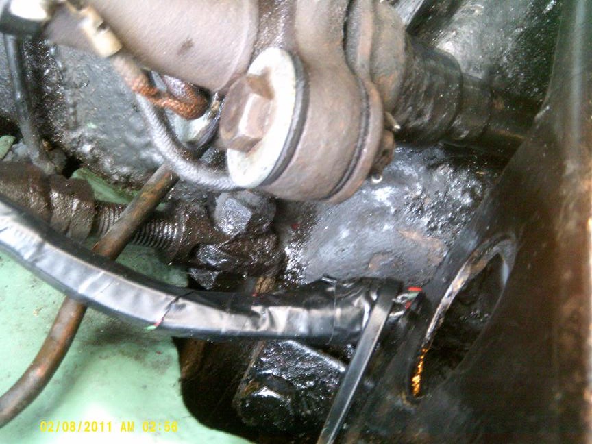
Two other jobs I did this day was to fit a tie-wrap to the wiring loom by the steering column’s lower joint. When rotated this joint was too close for comfort to the loom! (see photos). And I stripped off the tatty paint from the rocker cover, rubbed it down and sprayed it with Hi-Temperature silver paint from Halfords.
Neil Cairns.